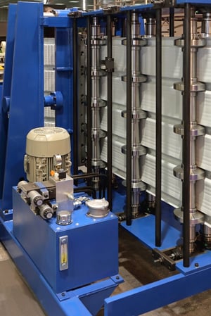
 Most conventional metal fabricators have the ability to accommodate almost any part design requests, as long as you’re willing to cover the associated costs. With a proper roll formed part, there are no additional costs or considerations: increased lead times are nonexistent, scrap is reduced to virtually nothing and your designed part is produced efficiently and with great repeatability.
This blog post aims to help those who are interested in the basics of creating an efficient, cost-effective part.
Choosing the Right Material
Great parts depend on choosing the right materials. While your materials should be high-quality, it’s important that you choose a material that ’s appropriate for the roll forming process and your intended application. So, what types of materials are the best choice for roll forming? First, aim to choose a material that’s readily available in coil or sheet form. The more difficult decision lies in choosing a metal that can tolerate bending to the desired radius; typically, the more ductile the better.
If you’re worried about choosing the right material, leave it to a professional. We here at CAMM metals would be happy to help.
Tips for Tolerances
The most important thing to keep in mind, in regards to tolerances, is to make them as loose as possible, while still maintaining proper functionality and quality expectations. Here’s a bit of information concerning the design aspects that influence tolerance fluctuations for different sections of roll formed parts:
- Accumulated Angular Tolerances: Variations in overall part dimensions beyond normal tolerance ranges are affected by accumulated angular tolerances.
- Multiple Hole Punching: Punching multiple holes causes an accumulation of tolerances. Although tolerances from each hole to the next may be held very closely, the overall deviation from the first hole to the last van vary by the sum of all intermediate allowable tolerances.
- Dimensional Hold: Outside dimensions can be held quite precisely when roll forming, though inside dimensions are subject to a variation of twice the strip thickness.
- Clustered Hole Patterns: Especially near the end of machined parts, clustered hole patterns may be punched if you’re using a a single die with multiple punches— this ultimately allows for very accurate hole to hole tolerances.
- Holes Close to Bends: Holes punched on or close to bends will distort into ovals or egg shapes, so be careful and plan your design and tolerances accordingly.
Important Guidelines for Roll Formed Parts
Below, we’ve included a few guidelines to help maximize efficiency and cost-effectiveness within your design. After all, you’re trying to create an excellent roll formed part, a part that is quick and simple to manufacture right away.
If you want to create a design that’s absolutely perfectly suited for your application (not just optimized for current manufacturing processes), your fabricator can take that design and make it work with their machinery. Of course, it’s important to keep in mind that the following guidelines are just that— they can be bent or broken when necessary.
1). Avoid Deep and Narrow Channels
It can be near impossible to produce a tall, leggy u-channel on standard machinery. In general, deep and narrow channels require large diameter forming rolls, which are more expensive to procure. Average sizes machines do best with a max depth of four inches.
2). Aim for Proper Leg Lengths
Due to the lack of leverage, short legs can be quite difficult to roll form in heavier gauge materials. Also, extremely long legs are difficult to form without specialty equipment. This also applies when hemming or bending material back on itself. However, there is a happy middle ground: if you’re worried about your legs being too short, make sure they’re a minimum of 3 times the material thickness past the tangent point. On the other hand, if you think your legs might be too long, you can make your section wider or open the sidewall at an angle.
3). Keep Punched Features Away from Edges and Bends
Punched features that are too close to the edge of the profile can distort the edge and/or the feature. Try to keep these holes located at least 1/2 of the diameter (or width) of the feature away from the edge of the profile.
Also, fabrications such as slots, notches, and holes can distort themselves or the part when placed incorrectly. Issues may arise when they’re placed too close to (or directly on) the bend line, as well as when they’re placed too close to the edge. To avoid this issue, the edge of the hole or slot should be at least three times material thickness away from the tangent point of the nearest bend.
4). Symmetrical Design
Unfortunately, asymmetrical parts are more likely to twist and cause other types of distortion in the finished stages. Designing your part with symmetry in mind can help to decrease or eliminate the probability of warping. However, many parts cannot be designed symmetrically; in these cases, CAMM Metals can accommodate these projects in roll tool design and machine setup parameters.
CAMM Metals | Roll forming for Metal Fabrication Projects
The best way to ensure an accurate metal fabrication project estimate is to start off with detailed, accurate product information. Plan ahead and communicate effectively, and you’re project is set for smooth sailing. Contact CAMM Metals and we would be happy to offer a free estimate on your next project.


